How to Install Fiber Splice Closure
Fiber Optic Cabinet closure is the equipment used to offer room for fusion splicing optical fibers. It also provides protection for fused fiber joint point and fiber cables. There are mainly two types of closures: vertical type and horizontal type. A large variety of fiber splice closures are designed for different applications, such as aerial, duct fiber cables and direct burial. Generally speaking, they are usually used in outdoor environment, even underwater.
For outside plant splice closure, there are two major types: horizontal type and vertical type.
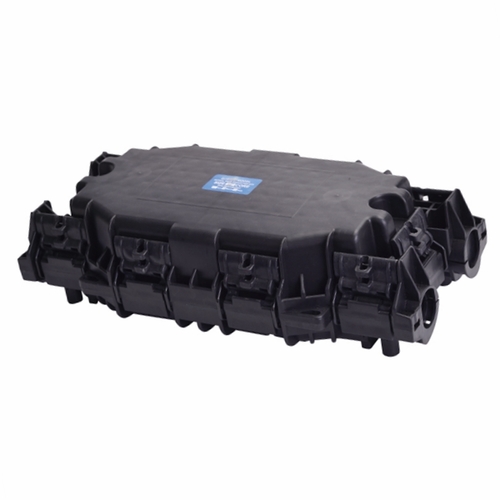
Horizontal type: Horizontal type splice closures look like flat or cylindrical case. They provide space and protection for optical cable splicing and joint. They can be mounted aerial, buried, or for underground applications. Horizontal types are used more often than vertical type (dome type) closures.
Most horizontal fiber closure can accommodate hundreds of fiber connections. They are designed to be waterproof and dust proof. They can be used in temperature ranging from -40℃ to 85℃ and can accommodate up to 106 kpa pressure. The cases are usually made of high tensile construction plastic.
Vertical type: Vertical type of fiber optic splice closures looks like a dome, thus they are also called dome types. They meet the same specification as the horizontal types. But they are designed for buried applications.
Splice closures provide room for splicing outdoor fiber cables together. Fiber splice trays are needed too. They provide the perfect protection for outside plant fiber cable joints.
Fiber splice closures accept both ribbon and round fiber cables. Each type (ribbon or round cable) fits respective requirement of different fiber splicing counts. They are widely used in optic telecommunication systems.
Here we will outline the main steps involved in fiber closure installation.
1. Components in the closure
Fiber optic splice closure kit usually includes: end plate, splice tray organizer, fiber splice tray, cover, cable grommets, grommet retainer, mounting bracket and hardware.
2. Fiber cable sheath preparation
2.1 Expose the rip cord. This step involves marking the location with a tape marker, ring-cutting the outer jacket with a sharp knife, removing the corrugated armor if applicable, and shaving off the outer jacket to expose the rip cord.
2.2 Remove the outer sheath. This step involves making a longitudinal slit down the outer sheath, peeling off the outer jacket and corrugated metal, and cutting the rip cord flush with the end of the corrugated metal.
2.3 Remove the inner jacket. This step involves using the rip cord under the inner jacket to slit it, cutting aramid yarns, cutting central strength member, and cleaning the filling compound.
3. Bonding and grounding hardware installation
Bond clamp installation. This step involves sliding the cable clamp over sheath, sliding the bond shoe under the corrugated metal, placing the bond plate over the bond shoe and securing the sheath grip.
4. Assembly of cables to closure
The preferable location for the two main cables is in the lower end plate port. If a third or fourth cable is required, it is easier to install it in the upper end plate port as a branch cable. This fiber optic splice closure is designed for two cables in each of its two ports. If only one cable will be installed in a port, the provided rubber grommet plug is used to substitute for the second cable.
4.1 Install cables to end plate. This step involves unscrewing knob and removing grommet retainer, positioning the end plate assembly, attaching the sheath grip to dielectric cables, sliding cables and sheath grip through, and securing sheath grip to backbone.
4.2 Grommet installation and external grounding. This step involves applying B-sealant, pushing the grommets into the end plate port, and applying more B-sealant.
4.3 Fiber unit preparation and distribution organizer installation. This step involves removing more loose tubes, separating each cable's loose tube into two groups, positioning the distribution organizer, securing the loose tubes to the distribution organizer, and securing the loose tubes.
4.4 Splice tray installation. This step involves placing the splice tray, fastening the end of the splice tray to the organizer, and installing cables, grommets and external ground.
4.5 Optical fiber splicing. This step involves splicing holder placing, fiber splicing and fastening the splice holder lid.
5. Fiber optic splice closure cover installation.
6. Closure mounting.
7. Reentry.
Recommended Products
-

Boltless Inline FOSC GJS-H020
Fiber optic closure is a passive component which can provide...
-

Fiber Optical Pedestal FOP-16B
FOP-16B fiber optical pedestal is designed specifically for ...
-

DOME Fiber Optic Splice Closure Empalmes verticales de fibra óptica 288cores GJS-D023
Fiber optic closure is a passive component which can provide...
-

Cajas Terminales ópticas para interior de edificios CTO-32E
CTO-32E is an optic distribution box for FTTH application wi...
-

Network Access Point NAP box FATM-0416AT
FATM-0416AT fiber access termination box is able to hold up ...
-

Optical rosettes Fiber Rosette FRB-1J
FRB-1J fiber rosette box is able to hold up to 1 subscribers...
-

OTDR-HJ2100 Series
The worldwide spread of broadband service has stimulated the...
-

Fiber Access Terminal Cajas de Distribucion box FSP-0316A
FSP-0316A fiber access termination box is able to hold up to...
-

Intermediate Optical Distribution Box 9 Cores---IODB-0309A
IODB-0309A box is able to allow the interconnections of the ...

 English
  中文简体
中文简体