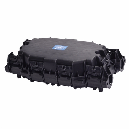
Fiber Optic Splice Closure Installation Method
Fiber preparation
1. Remove the cable jacket (if necessary, remove the shield and armor), then remove each jacket to expose the loose tube. Please follow the standard method recommended by the cable manufacturer for the specific method. The preparation length is 3 meters.
2. Clean the loose tube and core sheath with detergent, remove the excess filler sleeve, and sand the cable with 150 mm long sandpaper.
Cable installation
1. Select the seal with the smallest inner diameter according to the outer diameter of the cable and place the two seals on the cable.
2. Place the fiber optic cable into the appropriate manhole.
3. Connect the shield and ground.
4. Wrap the self-adhesive sealing tape between the two sealing rings so that the sealing tape is flush with the outer diameter of the sealing ring to form a cable sealing end.
5. Press the sealed end of the cable into the cable hole.
6. Pass the hose clamp through the cable rib mount and cable core bracket, secure the cable to the base of the connector box, and tighten the hose clamp until the hose clamp is tightened.
7. Place a nylon cable tie over the cable and cut off the excess length.
8. The remaining unused cable holes should be sealed with a plug. The sealing tape is also wound around the plug, which is required to be the same as in 5.2.4.
9. Wrap the reinforcing member around the countersunk screw of the splice tray holder and press it tightly.
Fiber optic connection
1. After placing the disc, prepare the fiber for 1.5 turns, then wrap the remaining fiber in the box.
2. Use a single-core buffer tube as a single-core fiber tray and a ribbon buffer tube as a ribbon fiber tray. A nylon cable tie is used at the entrance of the splice tray.
3. Dock two (abdominal) fibers according to the specified method. The connector snaps into the slot of the fuse unit. The extra length should be coiled on the disk.
4. Cover the splice tray and press it into place.
5. Determine the number of disks to be superimposed on the soldering plate based on the different Fiber Optic Splice Closure required for the splice case. The type of overlay of the welded plates must conform to the snap-in soldering unit of the fiber optic connector, as well as inspection and maintenance requirements. Each two welded plates are superimposed, and the rubber can be folded into six holes to respectively grasp the three tenons on the upper and lower plates; four rubber flaps have two symmetrical positions on each side of the disc, such as superimposing five for splicing The disc, the double-layer disc and the three-layer disc are fastened in the above manner, the three-layer disc and the four-layer disc are fastened, the four-layer disc and the five-layer disc are fastened, and the five discs are stably stacked. . When it is necessary to observe or maintain the welding state of a certain layer of disc, as long as the two folded sheets of the upper layer on one side of the disc are removed, the welded plate can be opened like a page.
Recommended Products
-

Boltless Inline FOSC GJS-H020
Fiber optic closure is a passive component which can provide...
-

Fiber Optical Pedestal FOP-16B
FOP-16B fiber optical pedestal is designed specifically for ...
-

DOME Fiber Optic Splice Closure Empalmes verticales de fibra óptica 288cores GJS-D023
Fiber optic closure is a passive component which can provide...
-

Cajas Terminales ópticas para interior de edificios CTO-32E
CTO-32E is an optic distribution box for FTTH application wi...
-

Network Access Point NAP box FATM-0416AT
FATM-0416AT fiber access termination box is able to hold up ...
-

Optical rosettes Fiber Rosette FRB-1J
FRB-1J fiber rosette box is able to hold up to 1 subscribers...
-

OTDR-HJ2100 Series
The worldwide spread of broadband service has stimulated the...
-

Fiber Access Terminal Cajas de Distribucion box FSP-0316A
FSP-0316A fiber access termination box is able to hold up to...
-

Intermediate Optical Distribution Box 9 Cores---IODB-0309A
IODB-0309A box is able to allow the interconnections of the ...

 English
  中文简体
中文简体